A machine is easier to understand when the job and the hardware can be seen together. A foundation rig has a task at the worksite. Inside it, assemblies, hoses, controls and fasteners connect that task to a power source. The photographs in my equipment archive let us move between those scales.
The views below come from separate photographs in the archive. They are a way to look at hydraulic equipment, rather than a reconstruction of one machine’s complete circuit.
Begin with the job

The wide view establishes the setting: tall equipment, a construction fence and buildings close around it. It also gives the component photographs a purpose. A motor or a valve becomes more interesting when there is a machine and a job to connect it to.
That connection takes more than recognizing a brand or a familiar housing. The machine model, its configuration and its documentation are what establish how a particular component is used.
Move into the assembly
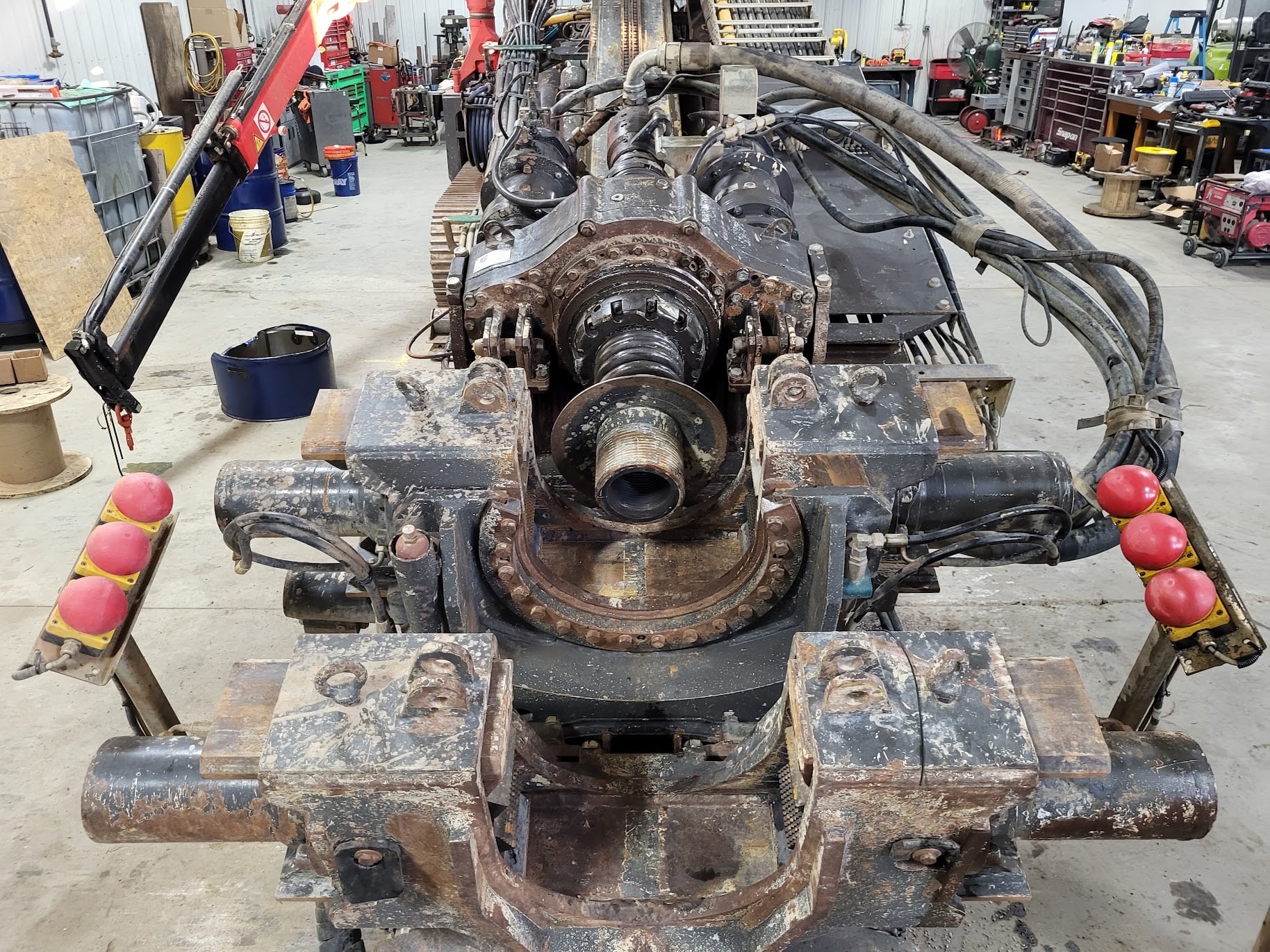
At this distance, the relationships become visible. Hoses lead into the assembly. Bolted structures hold its parts in place. Controls sit within the operator’s reach. The photograph helps locate those features without requiring a reader to know every component name first.
A useful next question is what each motion accomplishes. Rotation, a straight push or pull, and holding a load are different functions. They can call for different actuators, controls and mechanical arrangements.
Follow the power into motion
In a hydraulic system, a pump converts mechanical input into fluid flow. Pressure develops as that flow meets resistance. A hydraulic actuator then converts fluid power back into mechanical work. A motor provides rotary output; a cylinder provides linear motion. [1] [2] [3]
| Part | Basic job | Question for the machine |
|---|---|---|
| Pump | Supplies flow using mechanical input. | What drives it, and how is its delivery controlled? |
| Motor | Produces torque and rotation at a shaft. | What does that shaft drive? |
| Cylinder | Produces force and straight-line movement. | What linkage, carriage or tool does it move? |
For a motor, displacement, flow and the pressure difference across it help explain speed and torque. For a cylinder, piston area, pressure and flow help explain force and movement. The actual component ratings and machine arrangement are needed before applying those relationships to a real load. [1]
Read the connections
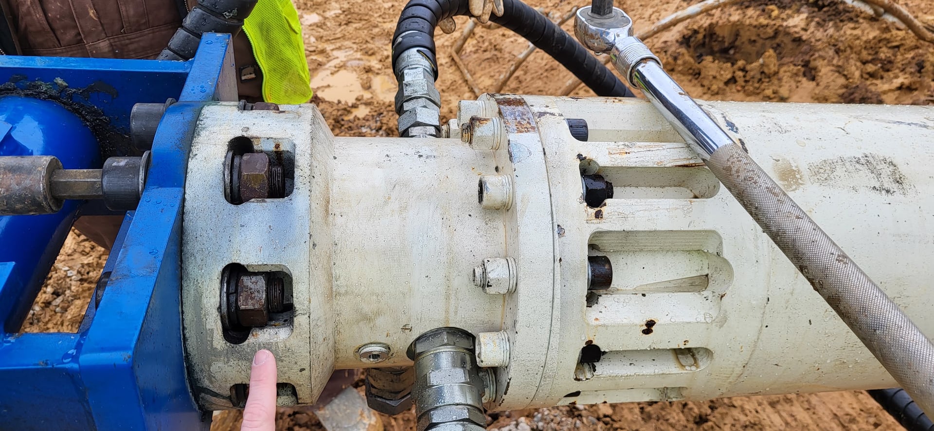
The close view preserves details that can disappear in a whole-machine photograph. The hose connections, mounting bolts and surrounding structure are all part of how the assembly fits into the equipment.
A hose disappearing out of frame cannot tell us where its other end goes. Nor does a photograph establish the pressure setting, the internal design of a valve or whether two similar units are interchangeable. The component identification, hydraulic schematic and manufacturer’s documentation supply those connections.
Moving between the wide and close views is the useful habit: understand the task, locate the assembly, identify its parts, then check how they work together. That makes the photographs a starting point for understanding the machine.
Turn the photograph into a question
A simple way to use these views is to write two short lists: what the picture shows and what the machine documentation must explain. A visible hose connection belongs in the first list. Its destination, operating pressure and function belong in the second unless they are independently identified.
Then follow one intended movement. If a tool must rotate, ask where rotary motion enters the assembly and how it reaches the tool. If a carriage must travel, look for its guides and the actuator that may move it. These are prompts for investigation, not identifications of the pictured components.
That habit keeps the wide view useful after moving into the detail. Each close-up should answer a question about the job or reveal the next question to resolve. It also provides a disciplined stopping point when the photograph alone cannot support an answer.
Sources and photographs
- Parker: hydraulic pump and cylinder formulas. General relationships for flow, pressure, force, displacement and speed.
- Parker: orbital motor operating principle. Explains pressure acting through an internal gear arrangement to produce shaft torque; it does not identify the pictured assembly.
- Parker: Hydraulic Cylinder Specification Guide. General cylinder function and application requirements.
Photographs: the existing equipment presentation archive, Muncie Support_1.pptx. The three views are not presented as the same rig, one verified circuit or proof of a particular project outcome.